Ikea Dioder Arduino Control

Arduino Dioder Mod:
For those of you who do not know, the Dioder from IKEA is a RGB lighting device.
There are 2 models, LED strip ($50), and "Multi-purpose" ($40)
My testing and modification was performed with the one linked below
http://www.ikea.com/us/en/catalog/products/50119407
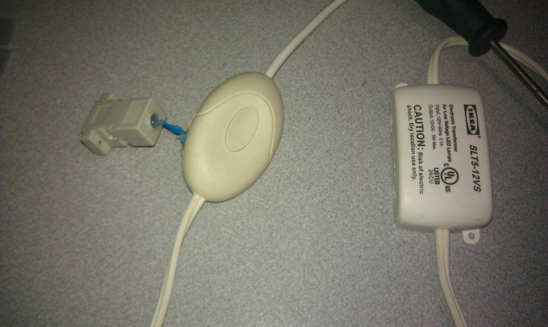
The internals pretty much consist of a 12f629 pic (Wii and Ps1 homebrew modchip for anyone paying attention), a button, Piezo speaker, and some various guts for providing and handling power.
I found a good deal of usable info on the device here: THANKS TO THIS GUY!
http://cauldrondevelopment.com/blog/2009/12/29/a-real-ikea-dioder-hack/
# It should be noted there are MUCH cheaper RGB LED strips available, I just happened to have one of these.
Phase 1: Controlling the Dioder
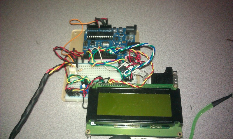
If you want to control the Dioder you need to first decide if you want to keep the original PIC functionality (ie. Do you want to permanently drive the Dioder with an additional device such as Arduino).
If you DO want to keep the original function, you'll need to cut the 5V trace going to Pin1 and then switch 5v to your External device and the internal PIC. Any SPDT should work, 5v to center pin, and then your Pic and Arduino on the outer pins (you could use an arduino to switch it, but it would require leaving your arduino attached...).
If you DON'T want to the original function, you can cut the trace, or just desolder the PIC for other uses. (the way I did it)
Here's an Example code to test the Arduino functionality with the Dioder (Or just about any PWM RGB)
Colors are output to Serial in IDE
If the Below Sketch doesn't work *exactly* matching the Serial, you've either got the RGB wired wrong, or your have power related issues!
//SKETCH--------------------------------------------------
/*
PWM RGB Blink Color Test Script
By EverestX
*/
int ledPinR = 3; //Red
int ledPinG = 5; //Green
int ledPinB =6; //Blue
// variable to store the read value
void setup()
{
pinMode(ledPinR, OUTPUT);
pinMode(ledPinG, OUTPUT);
pinMode(ledPinB, OUTPUT);
Serial.begin(9600);
}
void loop()
{
Serial.print(" Red");
analogWrite(ledPinR, 255);
analogWrite(ledPinG,0);
analogWrite(ledPinB, 0);
delay(3000);
Serial.print(" Green");
analogWrite(ledPinR, 0);
analogWrite(ledPinG,255);
analogWrite(ledPinB, 0);
delay(3000);
Serial.print(" Blue");
analogWrite(ledPinR, 0);
analogWrite(ledPinG,0);
analogWrite(ledPinB, 255);
delay(3000);
Serial.print(" Yellow");
analogWrite(ledPinR, 255);
analogWrite(ledPinG, 255);
analogWrite(ledPinB, 0);
delay(3000);
Serial.print(" Teal");
analogWrite(ledPinR, 0);
analogWrite(ledPinG,255);
analogWrite(ledPinB, 255);
delay(3000);
Serial.print(" Pink");
analogWrite(ledPinR, 255);
analogWrite(ledPinG,0);
analogWrite(ledPinB, 255);
delay(3000);
Serial.print(" WHITE");
analogWrite(ledPinR, 255);
analogWrite(ledPinG,255);
analogWrite(ledPinB, 255);
delay(3000);
Serial.print(" OFF");
analogWrite(ledPinR, 0);
analogWrite(ledPinG,0);
analogWrite(ledPinB, 0);
delay(5000);
}
//SKETCH--------------------------------------------------
You will need to modify the case of the Dioder with the pic inside to gain control of the device.
There are 2 separate cases. The one with the button is the case in question.
Phase2: MOAR!
The above sketch does not utilize the IO options of the Dioder fully such as the Button or the Piezo, so here's the modification to the top sections of the sketch to add them.
//SKETCH--------------------------------------------------
int buttonPin = 2;
int buzzerPin = 4;
int ledPinR = 3;
int ledPinG = 5;
int ledPinB =6;
void setup() {
pinMode(buttonPin, INPUT);
pinMode(buzzerPin, OUTPUT);
pinMode(ledPinR, OUTPUT);
pinMode(ledPinG, OUTPUT);
pinMode(ledPinB, OUTPUT);
Serial.begin(9600);
}
//SKETCH--------------------------------------------------
I have a nifty project I'll release soon for this
| Attachment | Size |
|---|---|
| ard1.jpg | 115.65 KB |
| ard2.jpg | 125.69 KB |